
Search Blog
Quick Inquiry
Chat on WhatsAppHot Products
About Us
Zhanjiang Group is a professional manufacturer of smart access control systems with 10+ years of experience, providing high-quality automatic gates, boom barriers for global industrial, commercial and residential projects.
Read More →Get A Free Quote
Trackless Retractable Gate Complete Installation Guide
Introduction
The trackless electric automatic retractable gates operate relying on ground navigation magnets without pre-buried tracks, featuring short construction cycles and low maintenance costs, which have become the mainstream solution for factory,school,industrial park entrances. Most novice constructors, maintenance technicians frequently encounter faults such as gate deviation, limit failure, motor burnout and abnormal operating noise. This article sorts out the full-process standardized construction specifications, covering site survey, foundation treatment, magnet embedding, gate assembly, electrical wiring, commissioning and final acceptance. It is universally applicable to stainless steel and aluminum alloy trackless retractable gates for zero-basement operators.
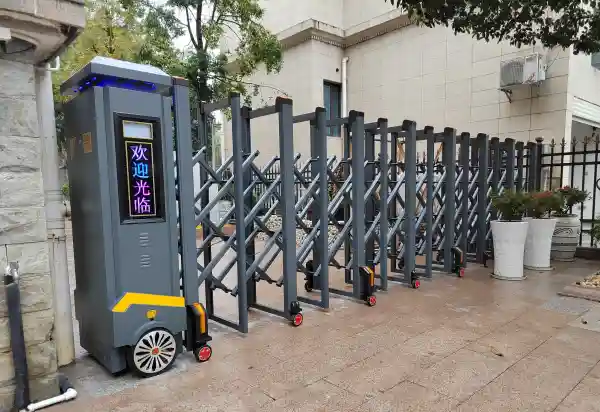
Why Choose a Trackless Retractable Gate?
No Ground Track Required
Traditional sliding gates require a track installed on the ground. Over time, the track may collect:
- Dust
- Sand
- Water
- Debris
This can affect operation and increase maintenance requirements.
Trackless systems eliminate this limitation and provide cleaner entrance solutions.
Tracked Retractable Gate vs Trackless Retractable Gate Comparison
| Comparison Factor | Tracked Retractable Gate | Trackless Retractable Gate |
|---|---|---|
| Ground Track | Requires a metal track installed on the ground | No traditional ground track required |
| Installation | Requires accurate ground preparation and track alignment | More flexible for different entrance conditions |
| Maintenance | Track requires regular cleaning from dust and debris | Lower maintenance due to no exposed track |
| Appearance | Visible ground track after installation | Cleaner and more modern entrance design |
| Suitable Applications | Best for flat and stable entrance areas | Ideal for factories, commercial areas, and large projects |
| Long-Term Performance | Performance depends on track condition | Stable operation with intelligent guidance system |
Complete Trackless Retractable Gate Installation Process
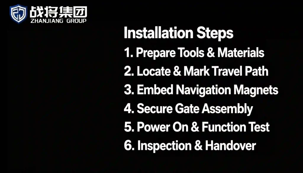
Step 1. Pre-construction Preparation
1.1 Determine the door clearance width in advance
1.2 Be sure to make sure the door is on a concrete floor
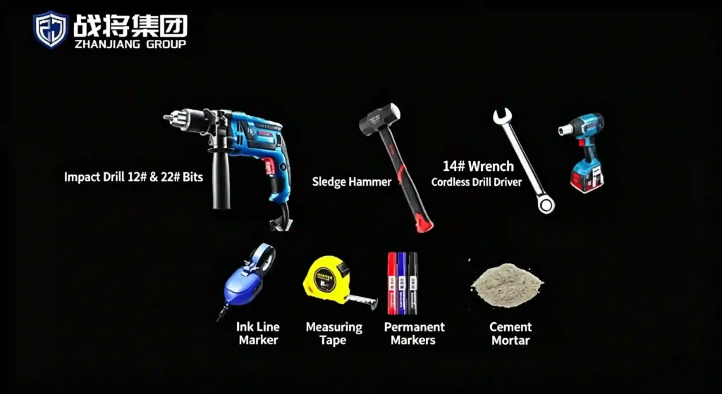
1.3 Full Construction Tool List
Laser level, 50m steel tape, ink marker, impact drill, M12 expansion bolts, 22mm drill bits, cement/waterproof mortar, hex wrenches, insulating tape, PVC conduit, utility knife, vacuum cleaner, rubber hammer, remote control pairing device, lubricant.
Step 2.Determine the framework
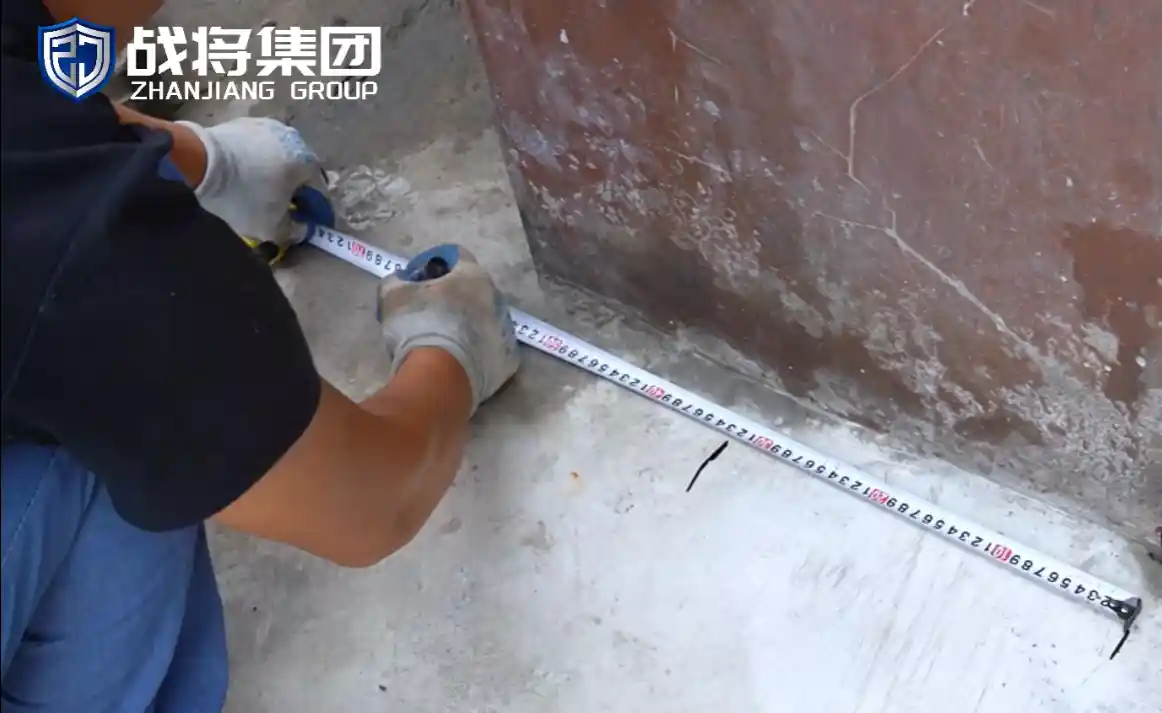
2.1 Defined pre-embedded trajectory
First confirm the width of the door body and record the middle size. Then use a marker to mark the width and middle size of the door body at the installation location.
2.2 Ground Alignment & Motor Base Reinforcement
Use an ink fountain to pop out a straight line along the marked center line, which is the navigation line.

2.3.1 Circular Guide Magnets
- Drill 3 cm deep holes on the centerline, fit one magnet every 15–25 cm in a straight line.
- All magnets N-pole up; reversed poles lead to S-shaped gate drift.
- Magnet tops flush with ground, seal gaps with waterproof mortar to protect rollers.
- Keep magnet path away from manholes, steel plates and rebar.
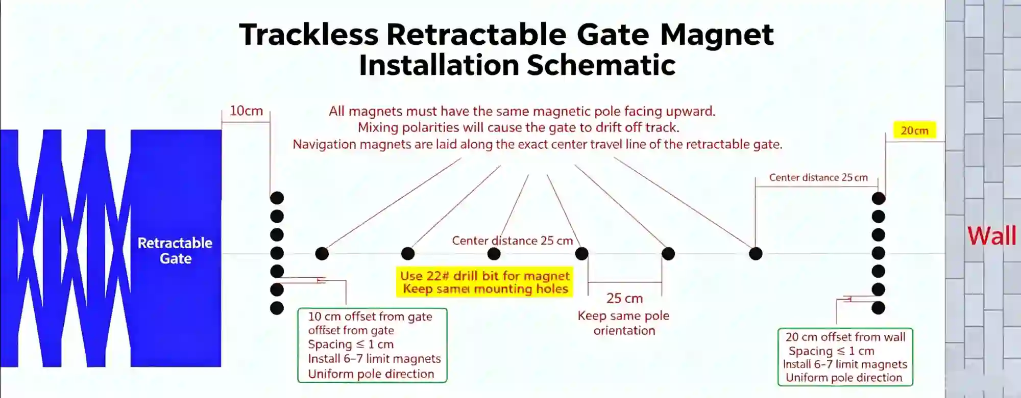
2.3.2 Square Limit Magnets (Stop Control & Anti-Collision)
Layout Rules
- Closing limit: 6–7 square magnets under the motor sensor when gate fully closed.
- Opening limit: Magnets 30 cm from the wall at full extension to prevent wall impact.
- Auxiliary anti-collision: Magnets 1 m before closing limit, work with infrared sensors for obstacle rebound.
Installation Steps
- Mark positions:
- Closing limit: 10 cm ahead of fully retracted door end; Opening limit: 20 cm from wall. Gap between two limits ≤1 cm.
- Mark guide magnet spots every 25 cm.
- Drill 2 cm deep holes with No.22 impact drill, clean holes afterwards.
- Fill holes with cement, insert all magnets N-pole up.Polarity check: Magnets attract = correct; repel = reversed.
- Magnets must sit flush with ground. Only seal surrounding gaps with cement, do not cover magnet surfaces.
2.4. Retractable Gate Door body fixed
2.4.1 Gate tail fixation: After full retraction, lock the gate tail cross pipe on solid wall with stainless steel angle codes and expansion screws to eliminate shaking;
2.4.2 Conduct manual push-pull tests for 3 times; proceed with electrical installation only if the gate runs smoothly without noise or deviation.

2.5 Power-on test (Step-by-step Guide for Starters)
2.5.1 Stage 1: Manual Clutch Test
Insert the clutch key and rotate 180° to disconnect the motor clutch. Push and pull the retractable gate manually to verify linear running, no jamming and ground scratching.
2.5.2 Stage 2: Travel Limit Debugging
Engage the clutch and switch on 220V power supply; double-check circuit short-circuit risks before power-on;
Trigger open/close commands via remote control; fine-tune navigation magnet spacing for slight gate deviation;
Adjust limit magnet position, control start-stop error within 2cm to prevent wall collision.
2.5.3 Stage 3: Safety Function Debugging (Mandatory Factory Standard)
Infrared Anti-collision Debugging
Install infrared beams at 1.2~1.5m height; the retractable gate shall stop and reverse immediately once blocking the sensing beam.
Obstacle Rebound & Emergency Protection
Obstacle rebound function: Simulate pedestrian or vehicle obstruction, the gate shall rebound automatically with moderate sensitivity to avoid false triggering;
Emergency stop test: Press the emergency stop button on the motor head to cut off power and lock the gate instantly.
2.5.4 Stage 4: Remote Controller Pairing Steps
Long press the mainboard pairing key for 3 seconds until the indicator flashes to enter pairing mode;
Press the gate-open key on the remote controller; steady indicator light means pairing success;
Add multiple remote controllers repeatedly and test long-distance signal response.
Step 3. Site Completion & Acceptance Checklist
3.1 Post-construction Finishing
Retighten all bolts secondly, lubricate hinge components to eliminate operating noise;
Seal magnet embedding positions and pipeline interfaces with waterproof sealant for outdoor rainproof protection;
Clean construction waste and wipe surface stains on the retractable gate.
3.2 Self-acceptance Checklist
Straight navigation magnets with unified magnetic poles, no gate deviation
Firm motor base, no shaking or loose expansion bolts
Flexible gate retraction, all casters grounded without abnormal noise
Accurate travel limit, no wall collision during operation
Valid anti-collision, obstacle rebound and emergency stop functions
Waterproof cabling, reliable grounding and qualified leakage protector
Stable remote control signal, multi-controller compatible pairing
Unobstructed ground drainage, no water soaking on working area
Complete accessories without deformation or paint peeling
Trackless Retractable Gate Applications
| Application | Why Choose Trackless Gate |
|---|---|
| Factory Entrance | Heavy traffic and frequent operation |
| Logistics Center | Requires reliable access control |
| Residential Community | Clean appearance and safety |
| Government Project | Customized design requirements |
Why Choose Zhanjiang Trackless Retractable Gate?
As an automatic gate manufacturer in Foshan, China, Zhanjiang Group focuses on providing:
✔ Factory-direct solutions
✔ Customized automatic gate systems
✔ OEM cooperation
✔ Project support
✔ International market service
For distributors, contractors, and project developers looking for reliable automatic gate solutions, we provide professional manufacturing support from design to delivery.
Need a Customized Trackless Retractable Gate Solution?
FAQ for Trackless Retractable Gate Installation
Q1: Why does the gate run in S-shape and deviate sideways?
A1: Mostly caused by inconsistent magnet poles. Ensure all navigation magnets N-pole upward. Other triggers: uneven magnet spacing (exceed 25cm), navigation line close to steel bars/manhole covers, or unlevel magnet surface.
Q2: How to quickly check reversed magnet poles on site?
A2: Put two magnets together. Mutual attraction means correct installation; mutual repulsion means reversed poles, adjust immediately.
Q3: Can I cover the installed magnets fully with cement?
A3: Forbidden. Keep magnet tops flush with the ground. Only seal surrounding gaps with cement or waterproof mortar; full coverage will block magnetic induction and cause navigation failure.
Q4: What is the standard spacing for round navigation magnets?
A4: Install one magnet every 15–25 cm along the centerline; drill 3cm deep holes for navigation magnets, 2cm deep holes for limit magnets.
Q5: The gate cannot stop automatically when fully opened/closed?
A5: 1. Excessive distance between opening and closing limit magnets (keep gap ≤1cm); 2. Insufficient quantity of closing square magnets (install 6~7 pieces); 3. Offset installation position of limit magnets, recalibrate and re-embed.
Q6: The gate hits the wall when fully opening?
A6: Install opening limit magnets 30cm away from the enclosure wall. Fine-tune magnet position to control start-stop error within 2cm.
If you need retractable gate solutions, installation drawings or free professional technical guidance for factory and large engineering projects, check our [Automatic Retractable Gate ] or contact us via WhatsApp:+8618927792680
We’re Here For Any Service
We’d love to hear from you, if you have any questions, please let us know and we’ll get back to you in the shortest possible time!
- +86 189 2779 2680
- +86 189 2779 2680
- +86 189 2779 2680
- zhanjianggatemfr@gmail.com
One Response